Free Branch Circuit Monitoring(BCM) Collection And Billing
Branch Circuit Monitoring(BCM) is basically monitoring how much amperage is flowing through your electrical circuits. Every major electrical PDU/RPP vendor sells these. They have small current transformer(CT) rings that you run the hot side of your power through and then into the breaker.

These BCMs generally have a Modbus interface. It is generally Modbus RTU, which is the original serial implementation of Modbus. The RTU standard while running RS485 has the ability to address 256 hosts on a network, but they recommend no more than 32 devices on a single ring. Since you have more than one device in a single serial ring, each must be uniquely addressed.
Since I have far flung BCMs that stretch beyond the physical distance and also beyond the device number limitations I also use a gateway. The gateway of choice is the Babel Buster SP.

This guy isn’t cheap at $550, but it works and it works well. What this device allows you to do is to wire it into an Modbus RTU RS485 ring and to seamlessly convert that to Modbus TCP. Modbus TCP is a TCP/IP method of querying for Modbus values. The only configuration one has to do on the device is to set an IP address, then set your serial port settings(in my case tell the serial port to use even parity). Wire in your RS485, plug in your ethernet cable and away you gooooo!
Modbus TCP is somewhat similar to SNMP in the fact that you query a device at a specific register(similar to an OID in SNMP) and it will return a value. You can also write to Modbus. Modbus TCP differs because you hit an IP address and also specify a slave ID. Each device that is on the serial ring has a serial address assigned to it…which is also known as the slave ID. In the Modbus world you can have many slaves, but only one master. This being the case, you can only have a single device on a Modbus ring that queries other devices. This is another great bonus of using a gateway. You can have multiple systems query the gateway(Master device on the ring) and the slaves will answer.
So, how do we collect the data? There are serveral different ways. One way is to create an Human Machine Interface(HMI). One that I found and have used is Aggregate. To get an HMI to be a BCM interface can be pretty tedious. We could also use a commercial product like power logic. This will only cost you several thousand dollars. Orrrr, you can write your own…or use mine 😉
There is a windows based app called Modpoll. Modpoll is a free windows app that allows you to poll or write Modbus RTU/TCP registers/coils from any device. Using this I wrote a basic program that polls Modbus TCP BCMs and saves them to file. The program is designed to be run every 15 minutes as a scheduled windows task. The program uses a file named config.txt. The config file lists the BCMs to poll in the form of:
#IP,SlaveID,Desc
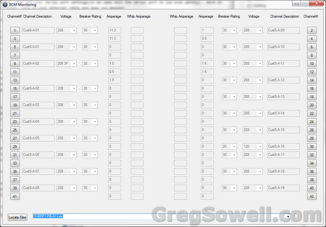
Then I wrote a BCM program that mirrors the look of an actual breaker panel. It loads up the captured files and shows you the amperage pulled from each circuit. It also gives you the ability to set a description/configured amperage/and power phase(120/208/208 3 phase) for each circuit.
Last there is a program that will process the collected information. It uses the description set on BCMs to coordinated customer information. What it does is calculate the kilowatt hours(kWh) for each circuit, then aggregate them for billing. The idea is that when you create a description on circuits you create a customer ID for each. So add descriptions like Customer1-A-1 or Customer1-A-2. All of Customer1’s info will be aggregated at the end of the month.

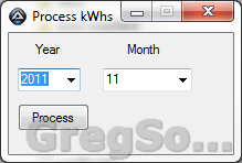
All you have to do is select the year/month and click the process button...how much easier does it get?
I’ve got the code and compiled configs here: BCM Poll FIles (1566 downloads)
Here’s the video of how it operates:


