

NES Power Glove Light Suit!!!
I’ve been cooking this up in my head for a while now, and here it is…or at least the first version of it. This is technically my 4th light suit to make, and my best yet 🙂
One of my favorite bands Hypercrush had a video where one of the guys was wearing a power glove that had lasers coming out of the ends. I had already made a light suit, and thought…what a waste. I thought “Why not control the suit with the power glove?” And thus it was born.
This new generation uses individually addressable LEDs that are controlled by a single pin…no pulse width, no mosfets…soooo siimple.
Since you are here to watch the video, here it is. The build log follows after.
Cut to 6:23 for the suit in action.
Materials are:
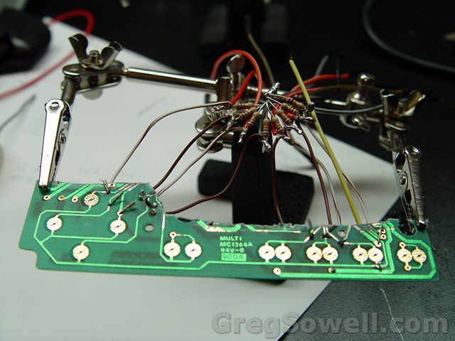
There’s a nice teardown here. I followed his example when I gutted the circuit boards, but my wiring differs, though.
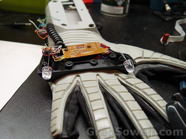
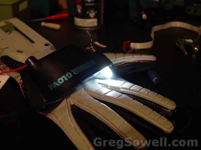
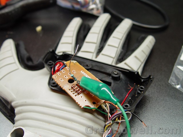
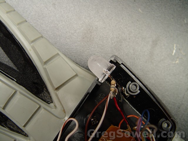
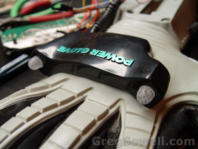
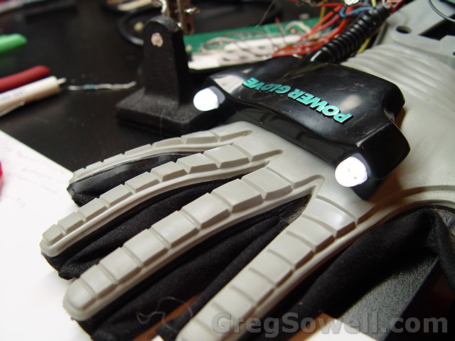
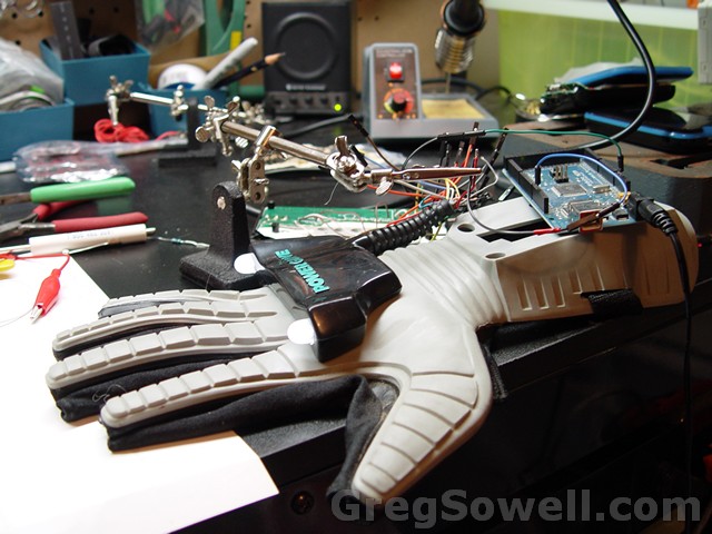
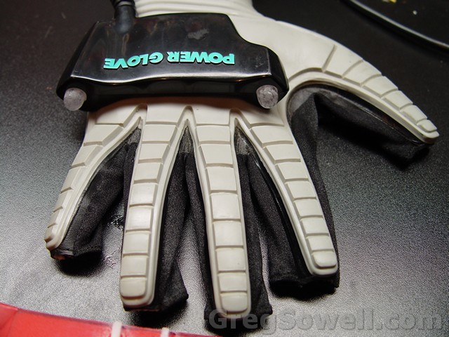
dry fitting the 10mm lights where the ultrasonics once were
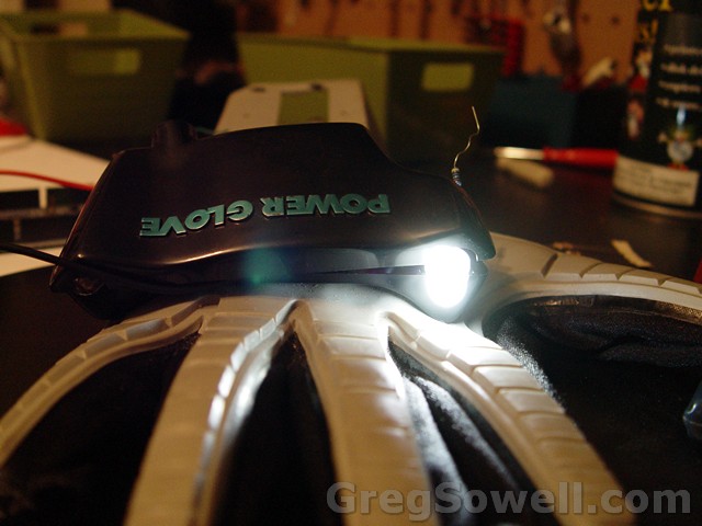
LED dry run
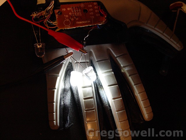
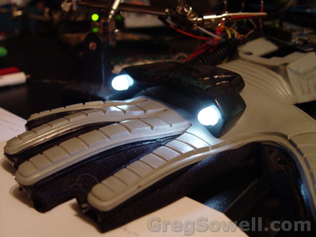
One frosted, one not
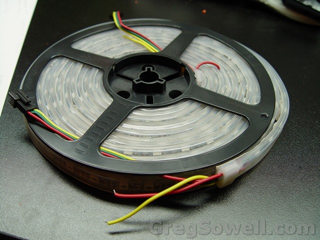
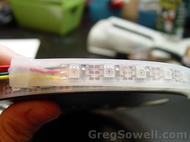
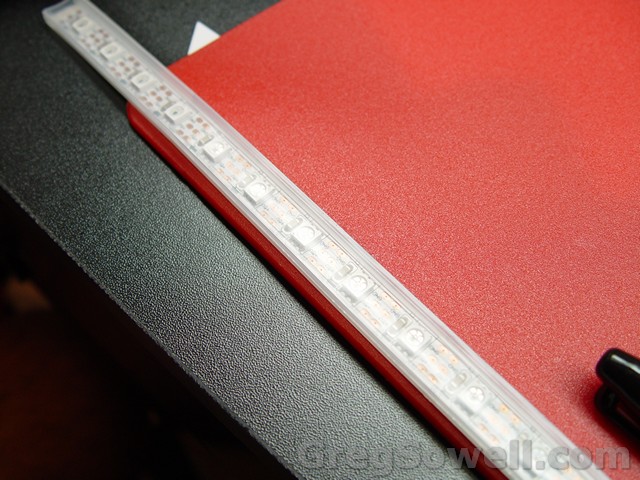
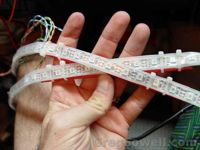
The 5 meter ws2812 strip
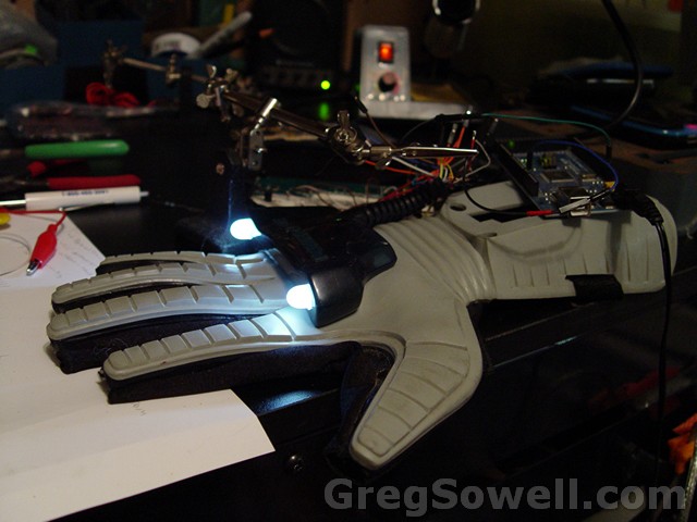
Test rig for the lights…just to try them out.
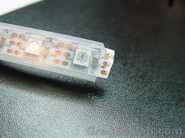
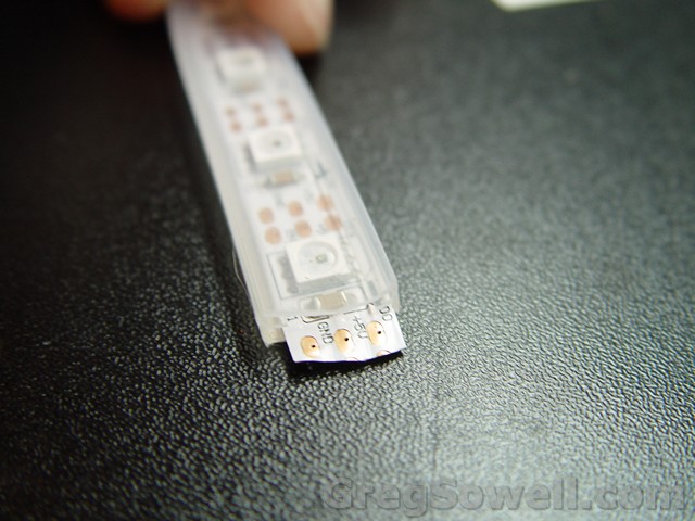
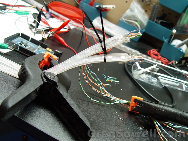
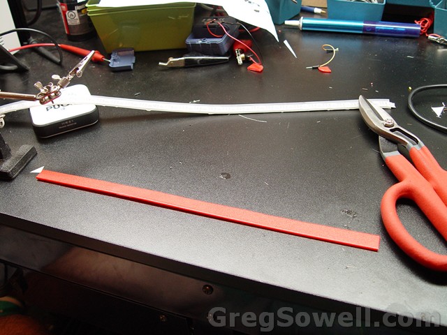
The strip cut in half. I then trimmed the rubber sheath back. They already have tiny holes ready to go!
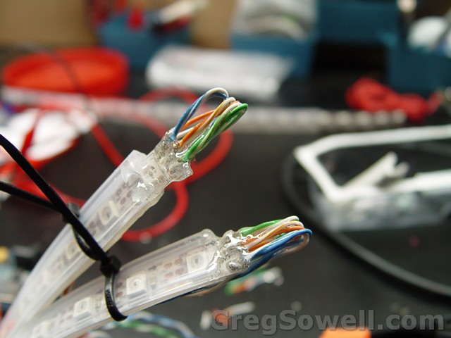
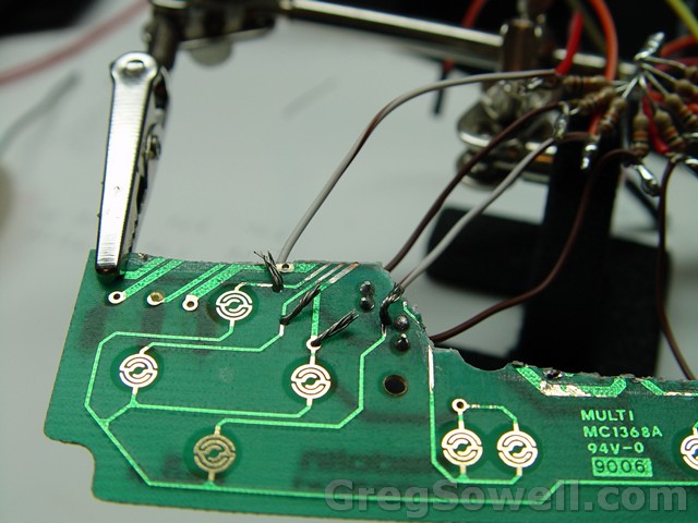
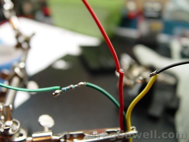
The data flows in a single direction, so you connect the out to the in. There are tiny arrows that show you. I take data and power/ground and tie them together.

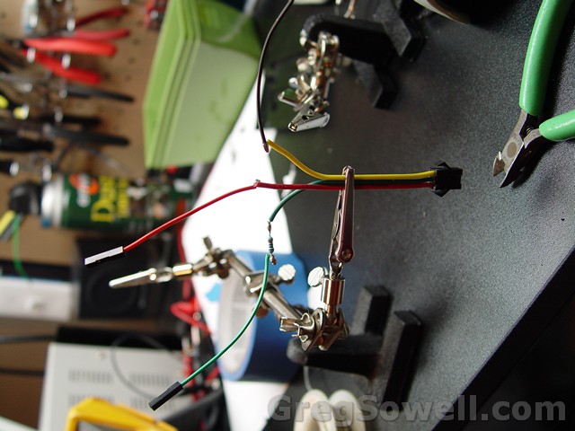
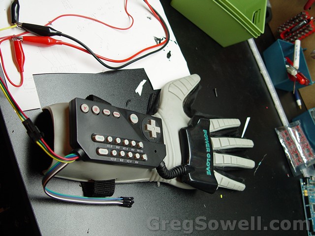
This is wiring into the bend sensors to test.
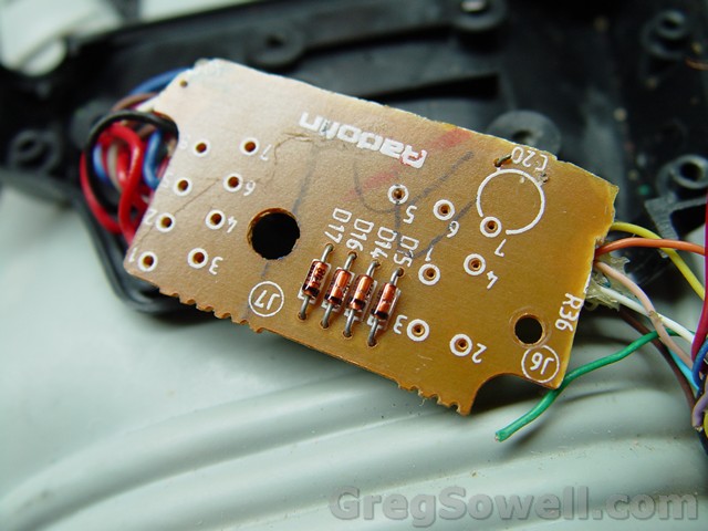
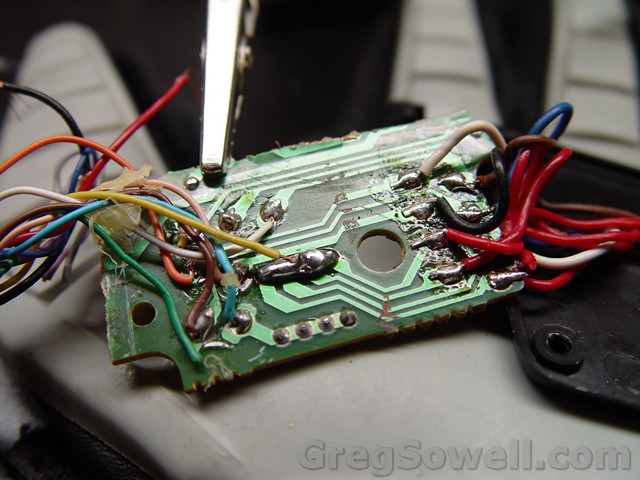
The diodes pull power reverse of what I wanted, soooo I bridged them all together to test.
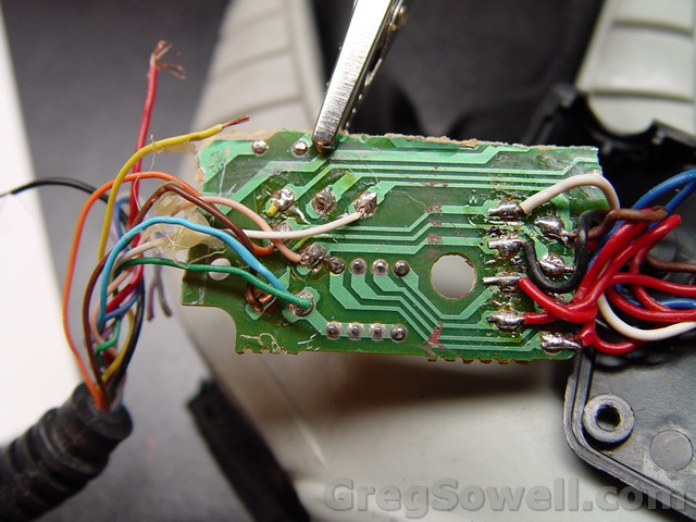
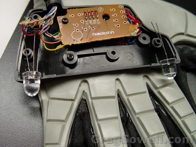
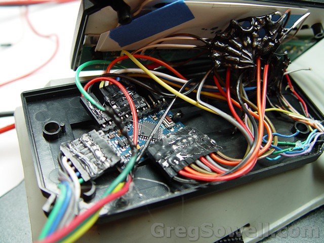
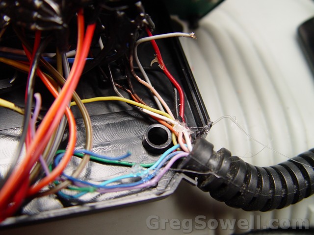
As you can see the top of the board is gone, and a lot of wires have been freed up.
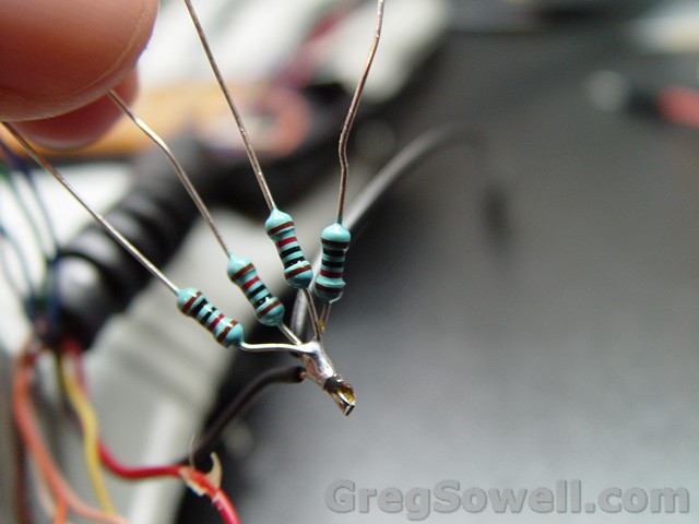
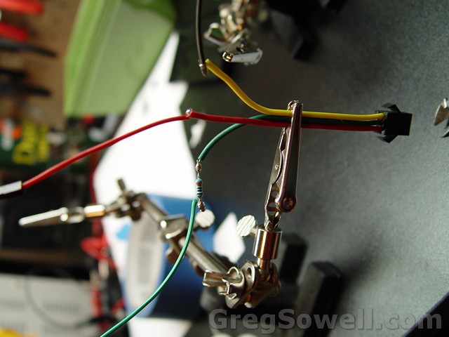
I used 10K resistors on each bend sensor to act as a voltage divider.
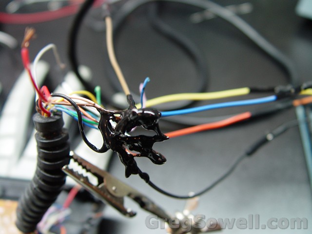
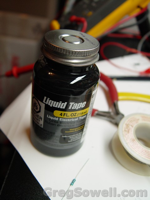
I’m using liquid electrical tape to protect everything.
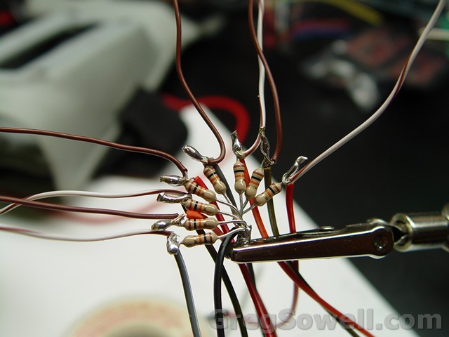
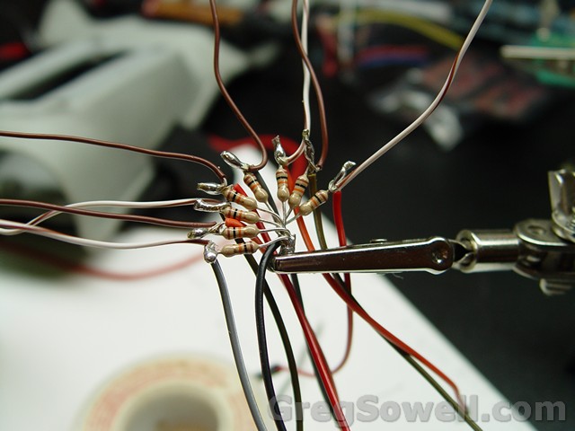
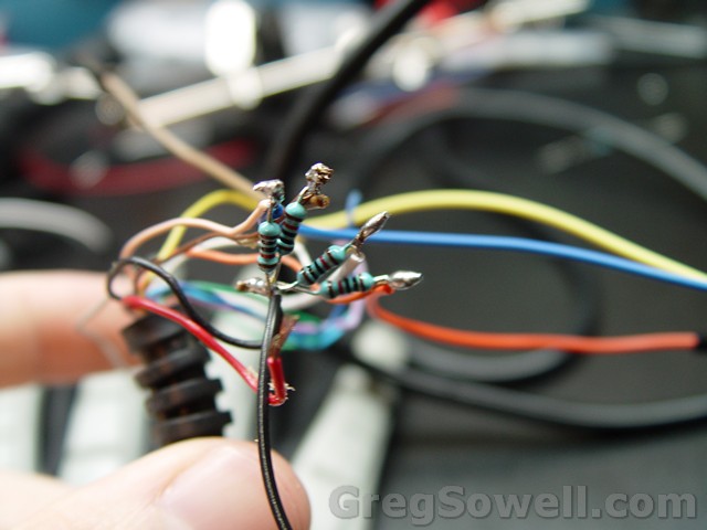
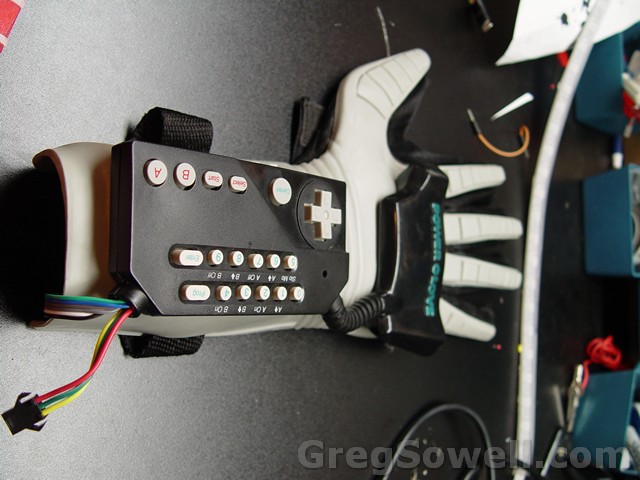
I’m using 10K pull down resistors for each button. This keeps the buttons digital pins from floating.


 /09/DSC06507.jpg” alt=”These are the buttons wired into the pull downs and then to the digital pins.” width=”640″ height=”480″ class=”size-full wp-image-4971″ /> These are the buttons wired into the pull downs and then to the digital pins.[/caption]
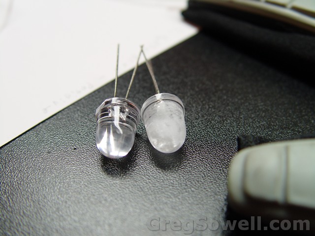
One frosted and one not. I like to sand them to diffuse the light.
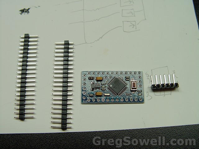
The arduino pro mini
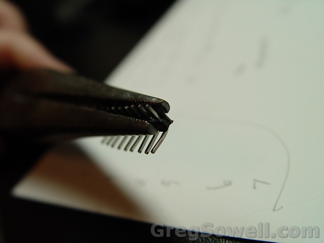
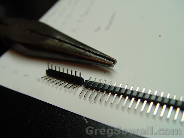
Pins bent to save space.
300 ohm protection resistor on the data pin.
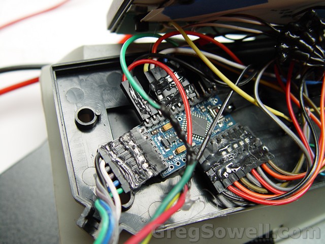
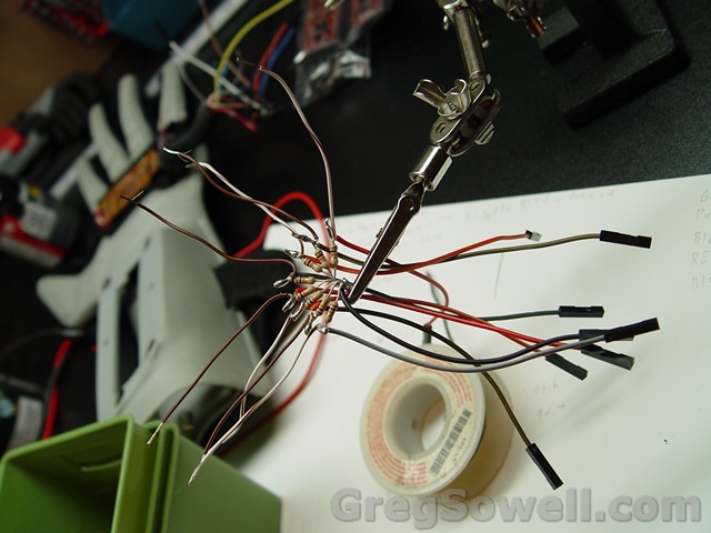
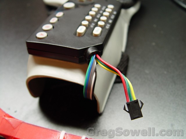
All the connections on. The ends are hot glued together to keep everything solid.
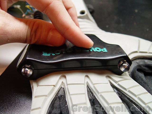
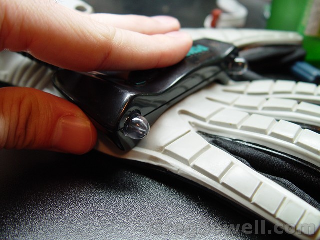
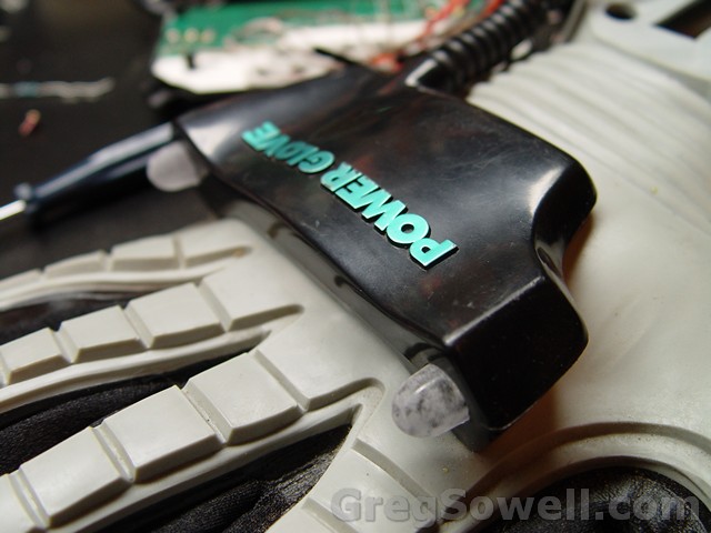
Glove all closed up.
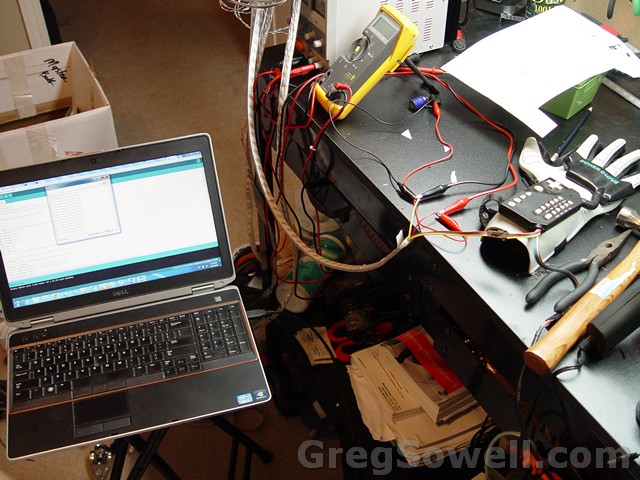
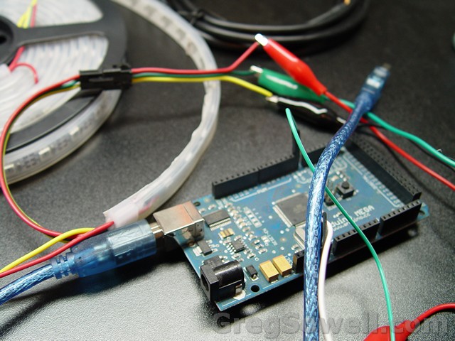
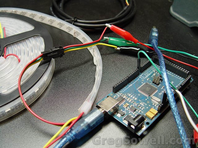
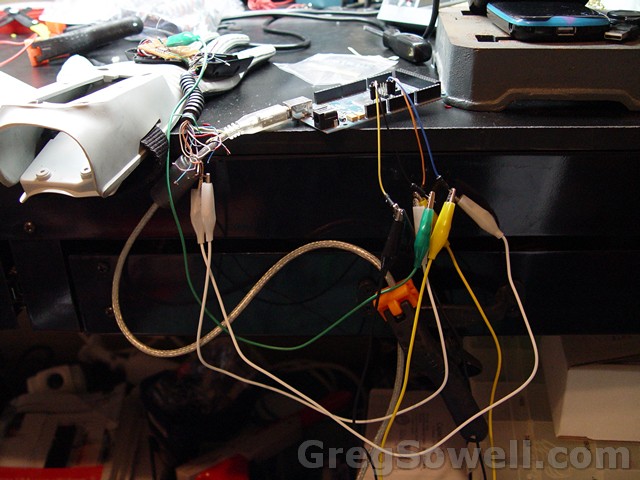
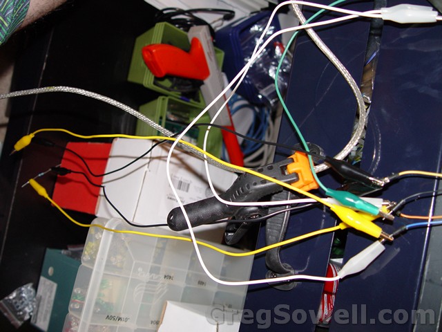
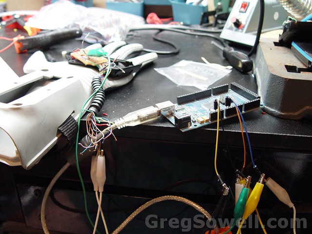
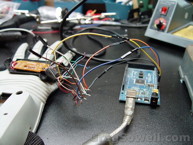
My test station setup.
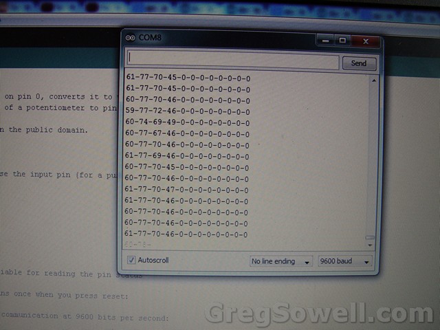
A sketch I wrote that shows bend sensor readings and button outputs.
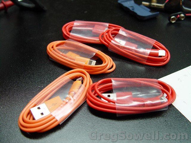
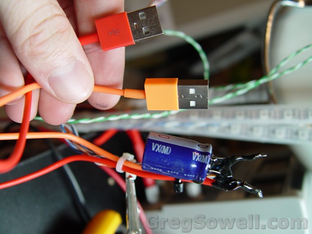
Cheap-o dollar store USB cables.
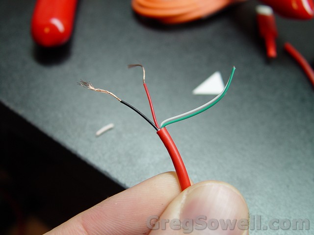
The gauge of the wire is thin, so I use two.
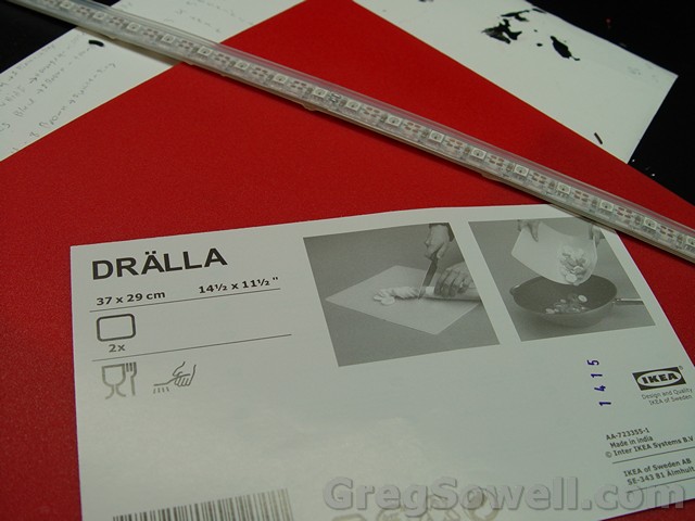
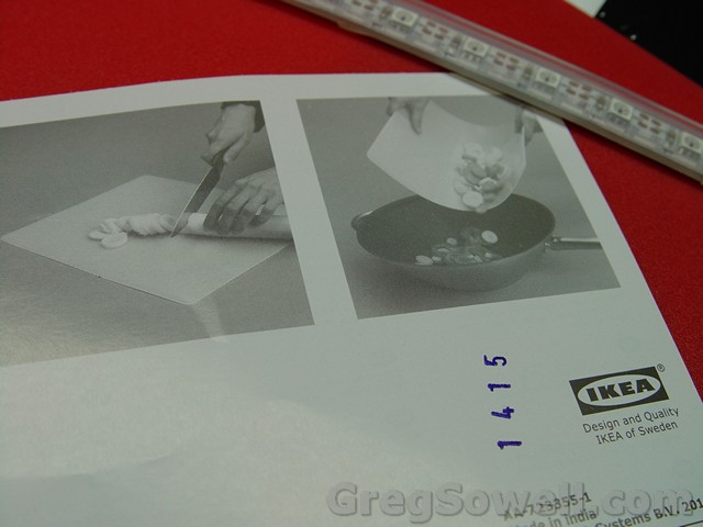
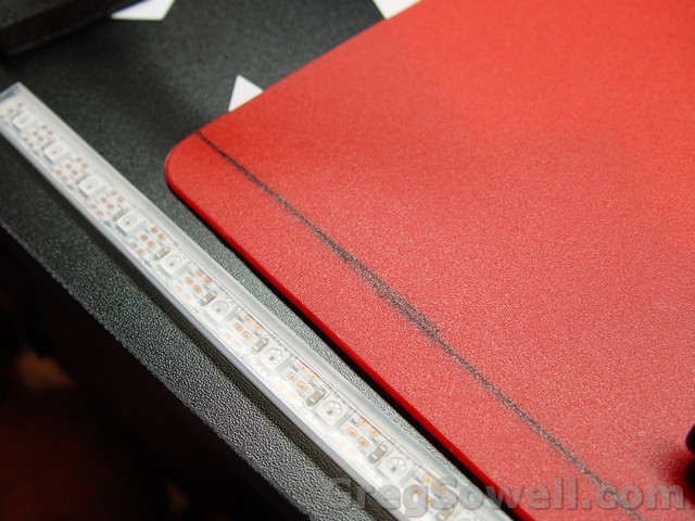
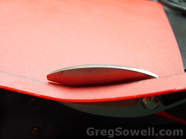
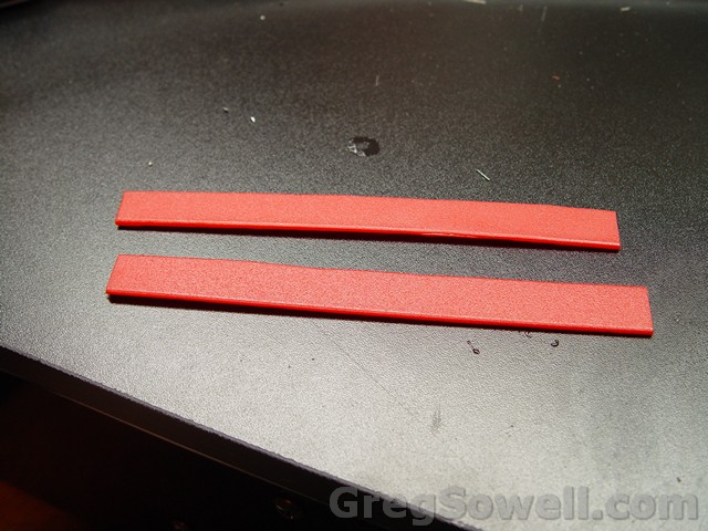
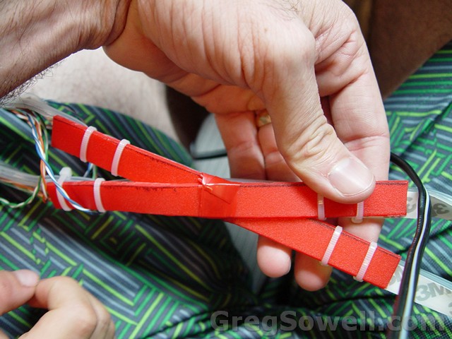
I’m using an Ikea cutting board to join the two pieces in the center. It is strong, flexible, and cheap( about a dollar).
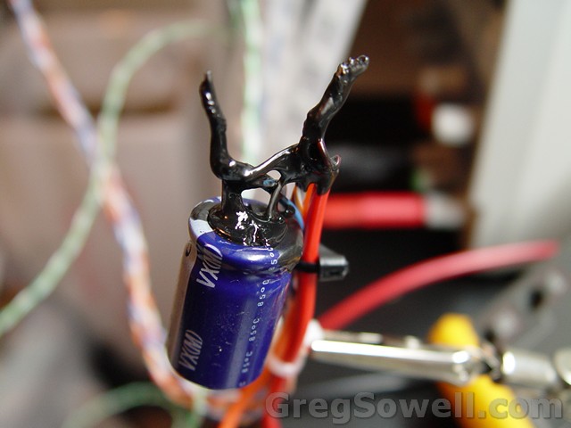
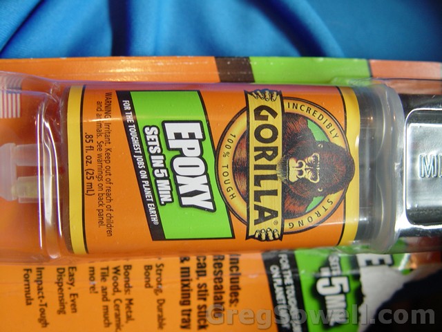
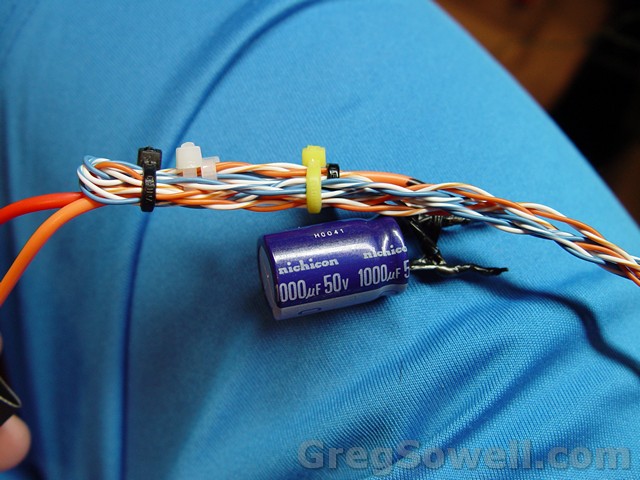
1000 uF cap…helps protect the LEDs.
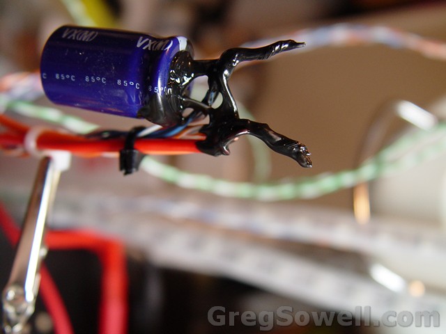
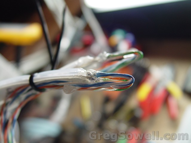
Everything joined together.
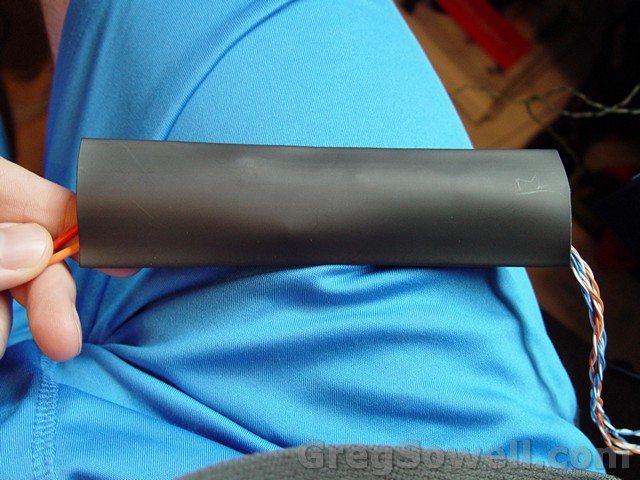
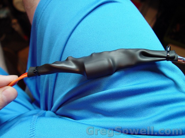
Heat shrinking the cap/power cables together…keeping it all safe and sound.
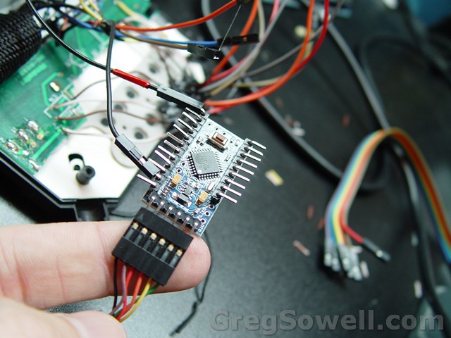
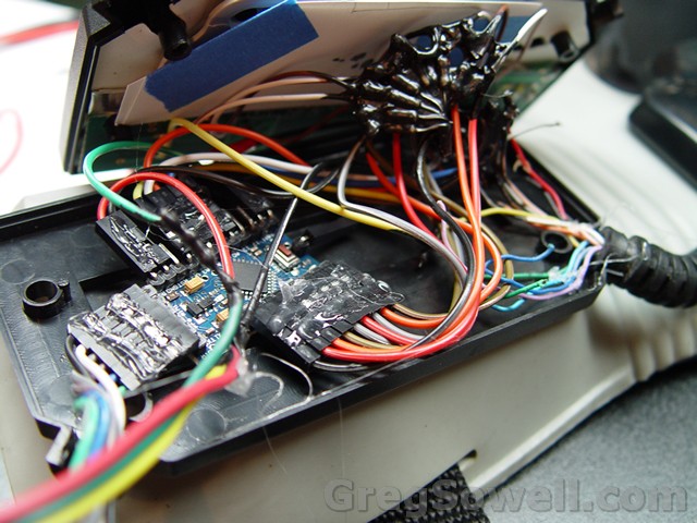
You can see both the FTDI cable and the LED strip connection. The arduino pulls power via the red and yellow wires.
Next step is to make a suit for each of my two boys, and a variation for my wife. I’ve got arduinos with radios so we can all be synchronized…muhahahaha
Let me know what you think in the comments kids!
Hahahahaha that is proper bad-ass man. I popped over to the site to look at your awsome vpn tutorial again and saw this suit vid. Rockin. Some glasses with leds either side (Kinda like orbital used to wear) would go nicely with the ones on the power glove. Nice work!
@Sam
Thanks mate! I’m ever evolving my projects…I think I need something for my head…whatever that may be 🙂
Dude, in case no one told you today…you rock! now jump on that long board a rip up and down the street with that gear. 🙂 thats what i would do.
@Cory
hehehe. I went for a stroll in the park this weekend, and ended up taking pictures with a bride and groom…let’s just say it gets attention hehehe.
Look you pioneered this idea and now they are making 10’s of dollars per suit.
gg-ca-glow-in-the-dark-lightsuit
I still like the original though.
Cheer,
@Cory lulz…eh