Monitoring Utility Power On The Cheap With Mikrotik
I was thinking while running the other day. How could one monitor utility power at a POP (Point Of Presence) without forking over your standard $200 for a monitoring device. So this is what I came up with:
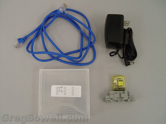
Supplies:
Cut your cable in half and then strip off a couple of inches of the jacket.
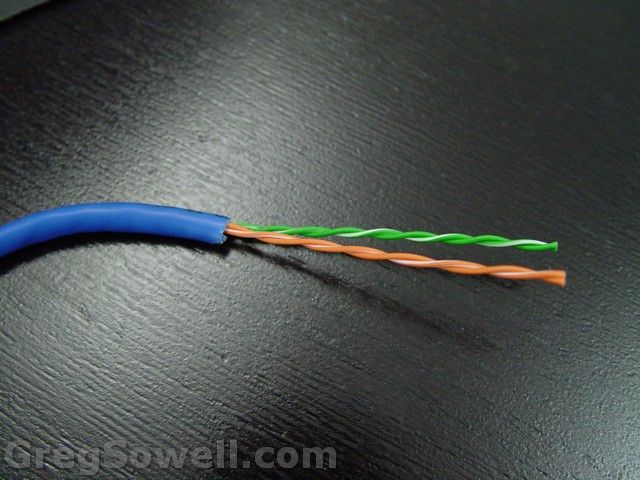
Then strip a little of the jacket from the remaining wires.
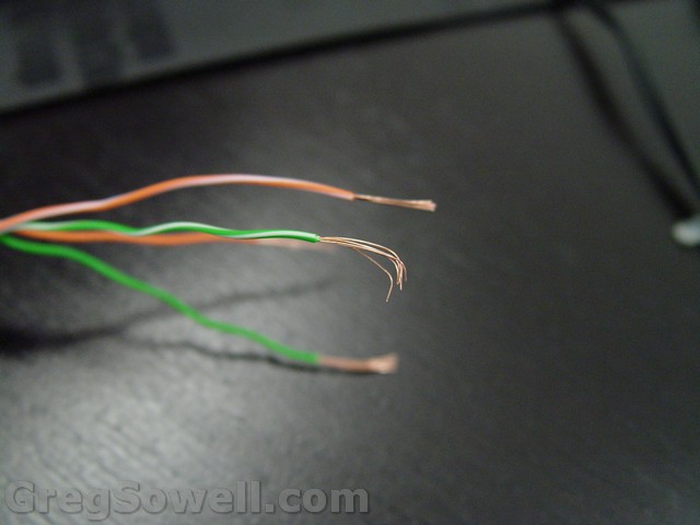
Wire the green/white to the common leg of relay # 1 or the first common if you are using a DPDT and the orange/white to the normally open (NO) leg.
Then wire the green to the second common leg (DPDT) or to the common of the second relay and the orange to the NO leg.
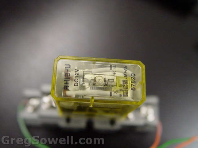
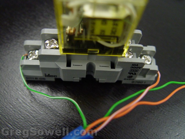
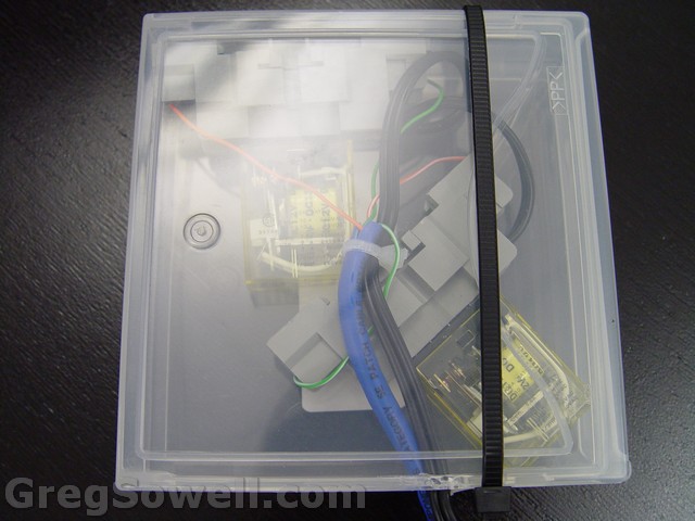
Then tie in your 12V transformer to the positive and negative polls on your relay(s). Throw everything into your plastic container and you are just about done.
At your POP, plug the router into the UPS and then plug the 12V adapter into the mains power outside of the UPS. Then plug the ethernet cable into an available port on the MTK.
When power is live on the 12V transformer, the relay is actuated and the cable we wired up is now looped up. With the loopback active, the port on your router comes up and the script running at the bottom of the page sends a message to you indicating that power is restored. When the power goes down, the UPS will keep the router up, but the relay will fail and thus the loopback will fail. The router’s script will see the change in port status and send you an email saying the port is down.
This script was written by a clever guy named Manuel, and I’ve adapted it to work in other situations.
1 2 3 4 5 6 7 8 9 | # Checking eth5 link status:
:global "ether5-state"
:global "ether5-laststate"
/interface ethernet monitor ether5 once do={:set "ether5-state" $status}
:if ($"ether5-state" != $"ether5-laststate") do={
/tool e-mail send from="Power <monitoring@$[/system identity get name]>" to="powerdown@gregsowell.com" subject="$[/system identity get name]: power status changed" body=("$[/system clock get date] \nInterface ether5 - link status changed to:" . $"ether5-state")
:log info ("Interface ether5 - link status changed to: " . $"ether5-state")
:set "ether5-laststate" $"ether5-state"
} |
Schedule the above script to run every 15 seconds or so.
If done correctly, you should be able to scrape all of this together for less than $15. If you spend $15 putting this together and it saves you a truck roll in the middle of the night, then it was well worth it!
Happy hacking my friends. 🙂


Hi. May be good idea write full scheme on connect the wires. Thank in advance 🙂
This is my kind of article! 😉
Thanks Greg, will use this for door open sensing as well.
This means a RB750 could do 4 sensors!
And how do you that?
http://tandem.ck.ua/ups_mtm-eng.php
@matrot2 – Cool looking product 🙂 Your UPSs also look interesting.
Hey Greg, Love your site. This is right up my ally and want to incorporate it into my tower battery backup units that we build. Is there any reason that I couldn’t use a Superlooper and only use one port?
Never mind Greg, ignore my post that’s what your doing! 🙂
awesome!! This might be the thing we have been looking for on our ZigBoxes
@Justin
I can always make a legit version of it 😉
Another clever way to do this is to recycle an old 411 or 911 board, particularly one that came back with a blown radio. It has to be a model with a readable voltage monitor. Run the power jack directly off a 12V transformer plugged into street power, and run 24V POE from a transformer on your UPS into the Ethernet jack. Normis says dual power is supported (http://tinyurl.com/zlsjtqe) and that the unit will use whichever is the higher voltage. Then just have a script in the device check its own voltage periodically and report as appropriate.
This still uses up a (precious?) ethernet port in critical equipment, but if that’s an issue, you could do it in a hAP and gain three more ports to boot.
@CD, true story. I prefer to complicate things as much as is possible.
Well, color me stupid anyhow. I just realized that at the site where I most need to do this, I’m already running a CCR, which has two power cord inlets standard, and their status is perfectly readable. So no need for electrical gymnastics; just split the power sources and write the script.
LOL…sounds about right